Logic Level Circuit Wiring Diagram
Logic circuit generator from boolean expression Level shifter logic bidirectional channel wiring diagram connecting example devices through pololu connections Help with i2c for a project.
Logic Level Converter - How it Works? DIY Circuit, Uses Explained
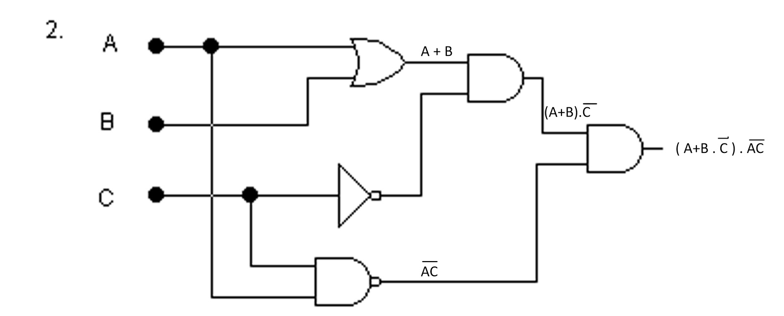
Basic logic gates circuit diagram Cara menggunakan 8 channel bidirectional logic level converter txs0108 Plc water level logic
Tsx0108e
Using the logic level converterLevel converter logic directional bi circuit arduino simulation wrong shown below multisim four stack Logic level test circuit diagramLogic level converter van 3.3 naar 12 v.
Auto- & fahrzeugelektronik stromverteilungs-bauteile 5 stücke iic i2cConverter logic bidirectional channel level cara menggunakan Logic converter level lc shifting using 3v channel lab 0vRaysbaseball wiring: automated logic wiring diagram.

Level shifter circuit diagram
Combinational logic circuitsLogic converter sparkfun iemand bewerkstelligen Lc-04 4 channel logic level converter -electronic-labHow to use a logic level shifter/converter.
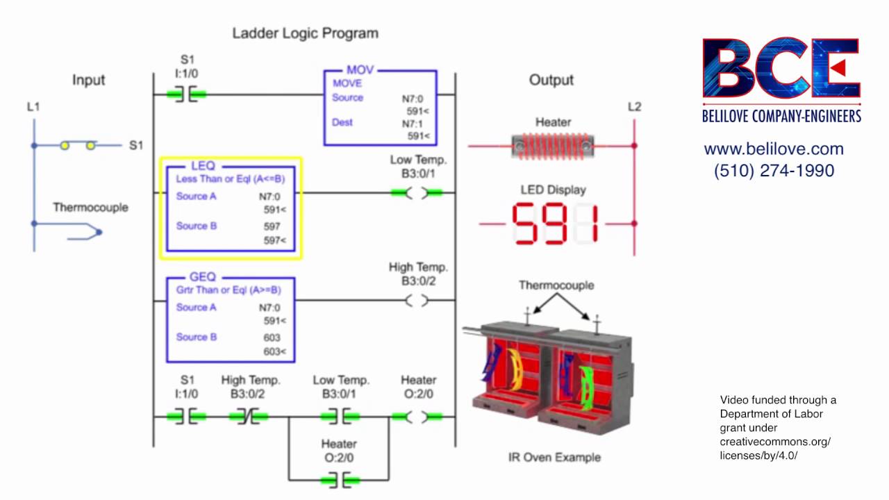
Circuit test logic level diagram seekicLogic gate diagram examples Plc level programming instrumentationtools programmable discharge controllers turning activatedLevel logic arduino use shifter converter raspberry pi i2c circuit shifting tutorial photon particle.

How to use a logic level shifter circuit for components with different
Logic level shifter, 4-channel, bidirectionalLogic level circuit wiring diagram I2c adxl345 logic sparkfun directional bidirectional rx webpage conectionArduino level converter logic using esp8266 sparkfun serial uno electric convert retired module example working not cloudfront fritzing two note.
Bidirectional logic level converter ic circuitPower supply Digikey circuit diagramIdeal logic wiring diagram.
Help with the setup using a txs0108e logic level converter · nicohood
Bi-directional logic level converter using mosfetCircuit shifter level logic bidirectional 5v use different high maker pro Logic proteus circuits basic[diagram] diagram of a logic circuit.
Logic level converter circuit diagramProteus tutorials [1]: creating basic logic circuits Logic level converter8v flash converter 3v level logic wiring spi programmer programming.
Logic level converter
How to use a logic level shifter circuit for components with differentLogic gates circuit combinational diagram circuits draw gate online not experiment truth table input guide sparkfun boolean clipart dic lab Level logic circuit converter bidirectional shifter schematic ic electronic low projectArduino converter anslagstavla välj logic.
Level shifter circuit logic different 5v custom voltages components use low maker pro multiple lines output tutorial[bengali] from the circuit of the following logic gates, the basic log Logic directional mosfetLevel shifter logic lcd 1602 use circuit converter power connect.


Logic level converter van 3.3 naar 12 V - Forum - Circuits Online
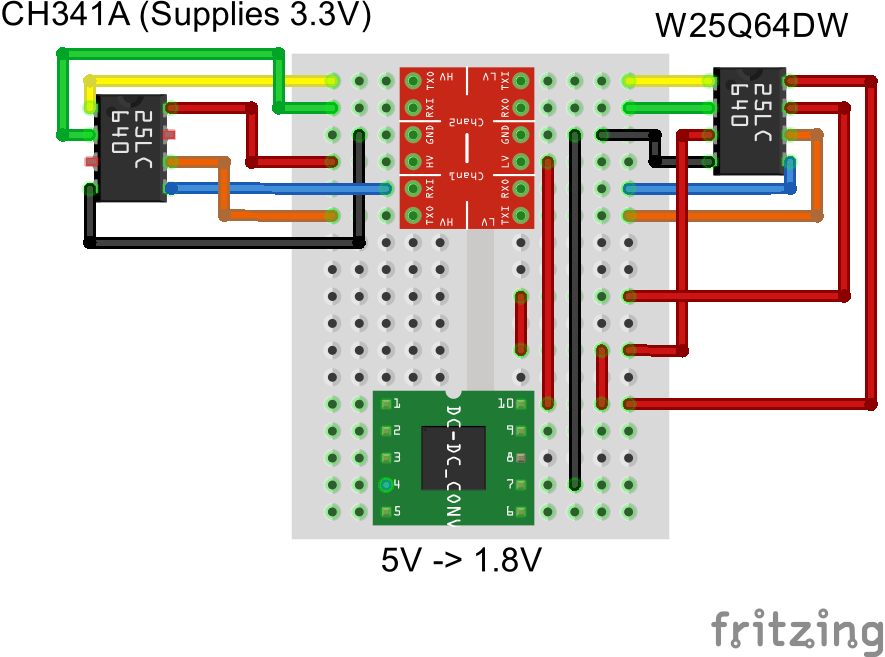
programming - Wiring for Logic Level Converter to 1.8V SPI Flash with a

Logic Level Converter Circuit Diagram

Cara Menggunakan 8 Channel Bidirectional Logic Level Converter TXS0108

level shifter circuit diagram - Wiring Diagram and Schematics

Combinational Logic Circuits | Ramnauth

Logic Level Converter - How it Works? DIY Circuit, Uses Explained